LRS - Oblique Plane Deformity Femur
| |
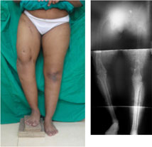 |
This patient had a congenital short femur with dysplasia of the hip on right side. She had undergone the lengthening of the femur earlier. She presented again with a progressive deformity as shown in the picture on the left side.
Now she had an apparent varus deformity with shortening of the right side.
When the full length x-ray was done it showed an oblique plane deformity which would require correction at two levels.
The planning for correcting this deformity was done by drawing the 90º line at the hip and the 87º line at the distal femur (at the knee). Another line intersecting these two lines was drawn along the femoral shaft. The points of intersection marked the two CORAs. |
|
| |
| |
| |
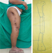
The picture the on the left shows the profile from the right side. Besides the scars from the previous surgery it shows a flexion deformity at the proximal femur.
The picture on the right shows tracing made from the x-ray. The tracing shows the proposed osteotomies and the corrected appearance.
The tracings make an important part of the preoperative planning of deformity correction. They help in simulating the correction. One can plan the exact site of osteotomy, the placement of pins/screws/wires and the placement of hinges and also come to know of the relationship of the individual bone segments and the final outcome. Therefore, one can correct any mistakes made during he planning even before going to the operating room. |
 |
|
| |
| Computer software are now available where the simulation of osteotomy and correction can be done directly on the digital x-ray image. |
| |
| |
| |
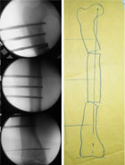 |
The picture on the left shows the composite of intra-operative c-arm pictures.
The schanz screws were placed perpendicular to the axis of the bony segment. Percutaneous osteotomies were then performed between the first and second set of schanz screws and the second and third set of schanz screws. Acute correction of varus and flexion deformities at the proximal osteotomy and correction of varus deformity at the distal osteotomy was done. The clamps and the rail were mounted and LRS (limb reconstruction system) fixator assembly was completed.
The picture on the right shows the tracing of the proposed correction. |
|
| |
| |
| |
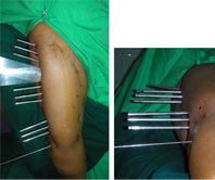
These pictures were taken during surgery to correct the oblique plane multilevel deformity.
The picture on the left shows the position of the schanz screws in the frontal plane. Three groups of schanz screws are visible. The proximal and distal group of schanz screws are divergent as compared to the middle group of screws (mimicking the double varus deformity of femur). The distal group of screws is parallel to the knee joint line (a reference wire was passed under c-arm guidance parallel to the knee joint). The arms of the goniometer have been placed parallel to the proximal and middle group of screws showing the divergence between the two. Once the osteotomy is completed the deformity gets corrected when the screws are made parallel to each other.
|
 |
|
| |
| The picture on right shows the position of the schanz screws in coronal plane. |
| |
| |
| |
 |
This picture was taken during surgery; shows the position of schanz screws in the sagittal plane. The proximal and middle group of screws are at an angle mimicking the flexion deformity of the proximal femur.
The slope between the middle and distal group mimics the normal femoral bow in sagittal plane.
Once the osteotomy is completed and the the proximal and middle group of screws are made straight the flexion deformity gets corrected. |
|
| |
| |
| |
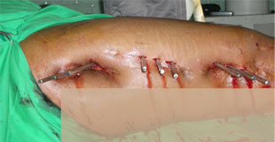
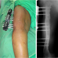
The appearance in the frontal plane once the varus angulations are corrected and the LRS (Limb Reconstruction System) assembly is completed.
The picture on the right is the x-ray appearance with the corrected bony axis. |
 |
|
| |
| |
| |
 |
| |
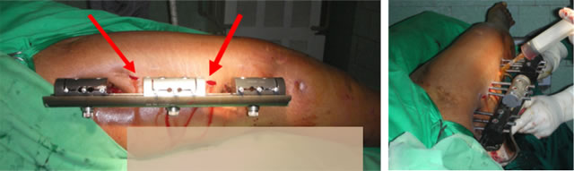
The appearance in the sagittal plane once the flexion deformity is corrected and the LRS (Limb Reconstruction System) assembly is completed.
Also seen are the small incisions (red arrows) through which the percutaneous osteotomies were performed.
The bottom picture shows how the incisions are cleaned thoroughly using a high pressure sterile normal saline and betadine solution.
For post-operative analgesia a long acting local anesthetic is infused at the pin sites and other incisions. We also like to use a pre-operative anti-inflammatory rectal suppository to cut down on the surgery induced inflammation and pain. |
| |
| |
| |
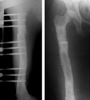 |
The final x-ray pictures just before fixator removal (left) and just after fixator removal (right).
The picture on the right is taken right after the fixator removal. The radiolucent shadow is the broken piece of threaded screw impacted in the bone. Also seen are the tracts left behind in the bone in the places where the schanz screws had been before removal. These tracts get filled up with new bone in about 3 weeks time. During this time we advise “careful weight bearing,” i.e. walk full weight-bearing with the aid of a crutch or a stick. |
|
| |